 |
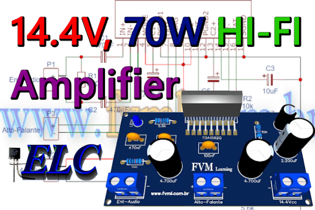
| Fig. 1 - 14.4V, 70W High Efficiency Power Amplifier using TDA1562Q IC + PCB |
The original project: Click Here!
The TDA1562Q IC is a monolithic Class H power amplifier in Bridge-Tied Load (BTL) mode in a 17-lead DIL-folded-SIL plastic package.
The device can be used for general-purpose audio systems, however, given its low operating voltage, between 8V and 18V.
We can use it in: Car Sound, Subwoofer Boxes, as well as applications powered by a DC power supply connected to the mains, such as: speaker system, guitar amplifier, TV Sound, or in portable audio like Boombox, Etc.
Features
- Very high output power, operating from a single low supply voltage
- Low power dissipation, when used for music signals
- Switches to low output power at too high case temperatures
- Few external components
- Fixed gain
- Differential inputs with high common mode rejection
- Mode select pin (on, mute and standby)
- Status I/O pin (class-H, class-B and fast mute)
- All switching levels with hysteresis
- Diagnostic pin with information about:– Dynamic Distortion Detector (DDD)– Any short-circuit at outputs– Open load detector– Temperature protection.
- No switch-on or switch-off plops
You might also be interested in:
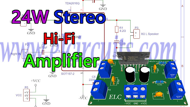
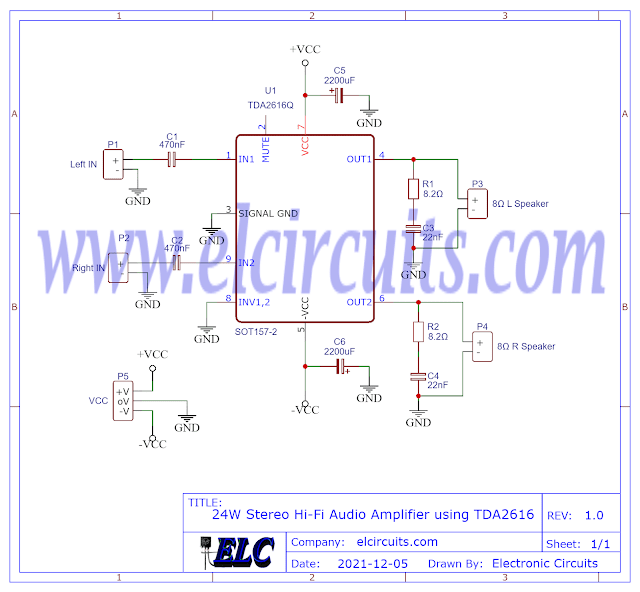
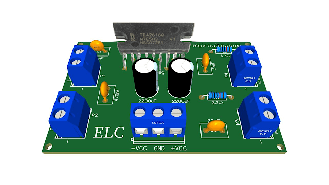
- 24W Stereo Hi-Fi Audio Amplifier using TDA2616 + PCB
- 68W Hi-Fi Audio Power Amplifier using LM3886T IC + PCB
- 4 x 50W High Power Amplifier, 14.4V - IC TDA7563A + PCB
- 320W Power Audio Amplifier, Powered with 14.4V - 2Ω with IC TDA7560 + PCB
- 100W RMS Audio Amplifier IC TDA7294 + PCB
- 200W RMS Stereo Power Amplifier with IC STK4231II + PCB
The Schematic
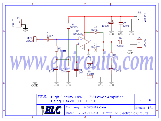
In Figure 2 below we have the schematic diagram of the High Efficiency Power Amplifier circuit and we can follow and analyze all the simplicity of the circuit, and as we can see, it is a circuit of easy assembly, and with few external components.
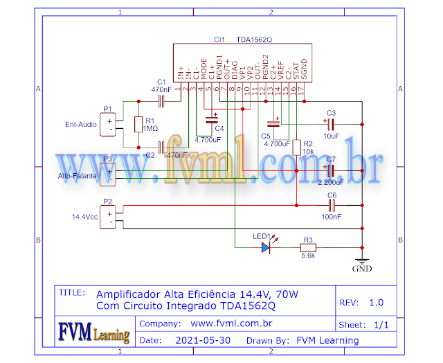 |
| Fig. 2 - Schematic 14.4V, 70W High Efficiency Power Amplifier using TDA1562Q IC |
Power Supply
This amplifier is powered by a simple positive and negative voltage type power supply, and has a supply voltage range that varies with a minimum voltage of 8V and a maximum voltage of 18V, the typical unstressed working voltage of the Integrated Circuit is 14.4V.
The power supply should have a current of at least 5 Amperes, to be used in mono mode, if mounting in the stereo, "two channel" version, the current should be doubled, and should also be provided with good filtering to avoid ripples in the system, which can cause noise in the amplifier.
The impedance of this amplifier to reach its full power is 4Ω, however we can set it to 8Ω, however we will not get the maximum power of the amplifier.
Component List
- Semiconductors
- CI1 ............ TDA1562Q Integrated Circuit
- LD1 ........... LED Light Emitting Diode
- Resistors
- R1 .............. 1MΩ resistor (brown, black, green, gold)
- R2 .............. 10KΩ resistor (brown, black, orange, gold)
- R3 .............. 5.6KΩ resistor (green, blue, orange, gold)
- Capacitors
- C1, C2 ....... 470nF Ceramic / Polyester Capacitor
- C3 .............. 10uF / 63v Electrolytic Capacitor
- C4, C5 ....... 4700uF / 25V Electrolytic Capacitor
- C6 .............. 100nF Ceramic / Polyester Capacitor
- C7 .............. 2.200uF / 25V Electrolytic Capacitor
- Others
- P1, P2, P3 ... Screw Terminal Type 5mm 2-Pin Connector
- Others ......... Heat sink for IC, wires, connectors, PCB, tin etc.
Printed Circuit Board
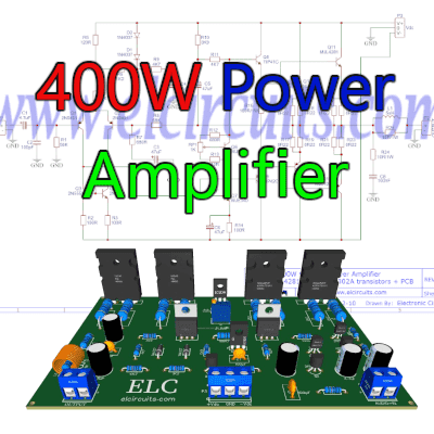
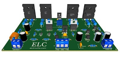
In Figure 3, we provide the PCB - Printed Circuit Board, in GERBER, PDF and PNG files. These files are available for free download, on the MEGA server, in a direct link, without any bypass.
All to make it easier for you to do a more optimized assembly, either at home, or with a company that prints the board. You can download the files in the Download option below.
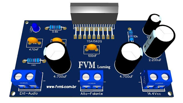 |
| Fig. 3 - PCB 14.4V, 70W High Efficiency Power Amplifier using TDA1562Q IC |
Files to Download, Direct Link:
Click on the link beside: GERBER, PDF and PNG files
If you have any questions, suggestions or corrections, please leave them in the comments and we will answer them soon.
Subscribe to our blog!!! Click Here - elcircuits.com!!!
My Best Regards!!!