 Português
 Español
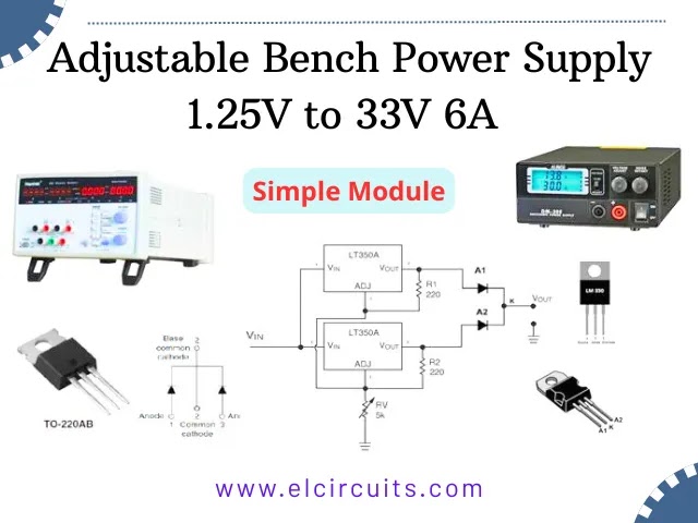
Adjustable Bench Power Supply 1.25V–33V 6A Module Tutorial
Complete module for 6A adjustable bench power supply
Hello electronics enthusiasts!
Whether you’re an engineer, electronics technician, designer, or hobbyist, an adjustable bench power supply is an indispensable tool in any workspace. The problem? Quality commercial power supplies tend to be expensive and, often, limited in current. But what if I told you that you can build your own robust bench power supply with 6 amperes of current and adjustable voltage from 1.25V to 33V for a fraction of the cost? Keep reading to find out how!
🧐 Why Build Your Own Bench Power Supply?
Professional bench power supplies are essential for testing and developing electronic projects, but the market offers options with two main limitations: low maximum current and high prices. Quality models easily exceed R$500.00, making them inaccessible for many students and enthusiasts.
This is exactly where our project shines! We’ve developed a fantastic module that offers:
- Adjustable voltage: 1.25V to 33V
- Robust current: Up to 6 continuous amperes
- Short-circuit protection
- Thermal protection
- Affordable cost and easy-to-find materials
📝 Required Materials
To build this adjustable bench power supply, we’ll use components that are easy to acquire and affordable. Many of them can be salvaged from old ATX power supplies!

Fig. 2 – Materials needed for the voltage regulator circuit
Component List:
- 2x LM350 ICs – 3A voltage regulators each
- 2x 220Ω Resistors (colors: Red, Red, Brown)
- 1x 5KΩ Potentiometer (preferably multi-turn for greater precision)
- 1x SCHOTTKY S16C45C Barrier Rectifier (16A) or alternatives
- 1x Universal printed circuit board or perfboard
- Heat sink (can be salvaged from an ATX power supply)
- Thermal insulators for ICs and rectifier
💡 Expert Tip: Don’t have a S16C45C rectifier? No problem! You can replace it with two common diodes, connecting anodes to the output of each LM and joining the cathodes to form a single output, as shown in the schematic.
🛠️ Step-by-Step Assembly
Now that we have all the components in hand, let’s start the assembly! Follow each step carefully to ensure the correct and safe operation of your module.
Step 1: Component Preparation
Start by mounting the two LM350 ICs and the SCHOTTKY rectifier on the heat sink. Attention: Don’t forget to use thermal insulators between each component and the heat sink to avoid short circuits!

Fig. 3 – Components mounted on heat sink with thermal insulators
Step 2: Board Assembly
With the components already mounted on the heat sink, fit them onto the printed circuit board. Follow the schematic to make the correct connections. The layout of components can be adapted according to your preference, as long as you maintain the correct connections.
Step 3: Resistor Connection
Solder the two 220Ω resistors as indicated in the schematic. They are essential for the correct operation of the regulator circuit.

Fig. 4 – Schematic Diagram Adjustable Power Supply Module 1.25V to 33V, 6A
Step 4: Potentiometer Installation
The voltage control potentiometer will not be soldered directly to the board. Instead, we recommend installing it remotely on the front panel of your power supply. To facilitate assembly and disassembly, we’ll use a two-pin connector.
💡 Expert Tip: For greater precision in voltage adjustment, consider using a multi-turn potentiometer. They allow for finer adjustments, essential for applications that require specific voltages.
Step 5: Soldering Connections
With all components properly positioned, proceed with soldering all connections. Make sure there are no solder bridges or cold joints that could compromise the circuit’s operation.

Fig. 5 – Soldering all connections on the universal board
Step 6: Remote Potentiometer Connection
Use a cable with a two-pin male connector to connect the potentiometer. This will facilitate the final assembly of your bench power supply, allowing the potentiometer to be installed on the front panel while the regulator module remains inside.

Fig. 6 – Cable with connector for remote potentiometer connection
🏋️♀️ Want More Power? Expand to 12 Amperes!
For those who think 6A is still not enough, we have excellent news! With a simple modification, it’s possible to double the current capacity to an impressive 12 amperes.
The secret? Simply build two identical modules to this one and connect them in parallel. This way, you’ll have an extremely powerful bench power supply, maintaining all protections (short-circuit and thermal) and precise voltage regulation.
⚠️ Safety Warning: When working with high currents like 12A, make sure to use appropriate wires and connectors for this capacity. High currents generate more heat and require greater care with thermal dissipation.
💡 Testing and Validation
Before powering your module, it’s essential to perform some safety checks:
- Confirm that the ICs and rectifier are properly insulated from the heat sink
- Check for short circuits on the board traces
- Test the continuity of the main connections
With everything verified, let’s connect a power supply. In our example, we used a 24V supply. Remember that the maximum output voltage will be limited by the input voltage minus the voltage drop across the components (approximately 1.95V).
Load Test
To validate our module under real conditions, we used as a load a car headlight halogen lamp (55W, 12V). According to Ohm’s Law, this lamp consumes approximately 4.58A (55W ÷ 12V).

Fig. 7 – Initial test with Halogen lamp as load
We adjusted the voltage to 13.52V (typical voltage of a car with an alternator running) and connected the load. The result? Excellent stability, with a voltage drop of only 0.4V under a load of 4.58A!

Fig. 8 – Load test with 55W halogen lamp
🔗 Related Content
If you liked this project, you might also be interested in these other articles:
- Adjustable Power Supply 1.25v to 57V, 6 Amps with TIP36C + LM317HV + PCB
- Adjustable Power Supply 1.25v to 33V, 3 Amps with LM350 + PCB
- Stabilized Power Supply 13.8V High Current 10 Amps with PCB
- Adjustable Power Supply 1.2V to 37V High Current 20A with LM317 and TIP35C + PCB
- Switched Power Supply SMPS 13.8V 10A using IR2153 IC and IRF840, with PCB
- Adjustable Power Supply 1.2V to 37V, 6A, Short Circuit Protection with LM317 and TIP36 + PCB
- Symmetrical Adjustable Power Supply 1.25V to 47V 10 Amps with Short Circuit Protection + PCB
📥 Download Files
Direct link: Download Files
🧾 Conclusion
Our 6A adjustable bench power supply project demonstrates that it’s possible to build quality equipment with low cost and high efficiency. The simplicity of the circuit, combined with the robustness of the components used, results in a reliable and versatile power supply for various applications.
Whether for testing prototypes, powering circuits during development or for use in your home laboratory, this adjustable bench power supply will certainly meet your needs with excellent performance and stability.
Detailed Video
For those who would like more details about the assembly process and testing, we’ve prepared a complete video on our YouTube channel. In it, we show each step in detail and share additional tips:
🤔 Frequently Asked Questions
We’ve gathered some of the most common questions about this project to help you:
❓ Can I use a transformer different from 24V?🔽
Yes! You can use transformers with voltages between 18V and 30V. Remember that the maximum output voltage will always be approximately 2V lower than the input voltage.
❓ Is it mandatory to use the SCHOTTKY rectifier?🔽
It’s not mandatory, but it’s recommended. SCHOTTKY rectifiers have lower voltage drop, which improves the circuit’s efficiency. You can replace it with common diodes as explained in the article.
❓ Do I need to use a specific heat sink?🔽
Not necessarily. Heat sinks from ATX power supplies are usually sufficient, but remember that the greater the dissipation, the better the performance at high currents.
❓ Can I add a digital display to show voltage and current?🔽
Absolutely! There are digital display modules with voltmeter and ammeter that can be easily integrated into this project for greater precision and convenience.
Did you like this project?
Leave your comment below sharing your questions, suggestions or experiences with bench power supplies! Your interaction helps us create more and more quality content for the electronics community.
Original article published on FVML (Portuguese) – December 13, 2018
✨ Our Gratitude and Next Steps
We sincerely hope this guide has been useful and enriching for your projects! Thank you for dedicating your time to this content.
Your Feedback is Invaluable:
Have any questions, suggestions, or corrections? Feel free to share them in the comments below! Your contribution helps us refine this content for the entire ElCircuits community.
If you found this guide helpful, spread the knowledge!
🔗 Share This Guide
Best regards,
The ElCircuits Team ⚡


