Showing posts with label Amplifier. Show all posts

Tuesday, December 14, 2021

400W Class AB Amplifier using MJL4281A and MJL4302A transistors + PCB

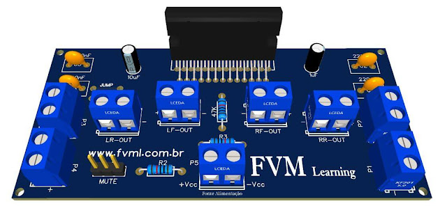
Fig. 1 - 400W Class AB Amplifier using MJL4281A and MJL4302A transistors + PCB

The amplifier circuit is 400W RMS per channel, if you want to make two of these boards, they will be 800W RMS, that is, high power with great sound quality and stability.

This amplifier circuit can be used for virtually any type of application that requires an amplifier of high performance, low noise and low distortion, and excellent sound quality.

It uses 4 power transistors on the output; two NPN transistors MJL4281 and two PNP MJL4302, forming a double pair of complementary transistors.

You might also be interested in:

The Power Transistors

The MJL4281A and MJL4302A transistors are power transistors designed for high power audio, they have a collector-emitter sustaining voltage of 350 V, high gain - 80 to 240, with the hFE = 50 (min) 8A collector current. And a low harmonic distortion, which makes a transistor exceptional for high power operation and audio quality.

The Circuit

The complexity of the circuit is at an advanced level, it is not recommended for those who do not have experience in electronics and in assembling amplifier circuits, you must have minimal knowledge at an advanced level to assemble this type of power amplifier.

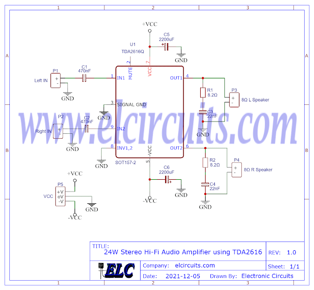
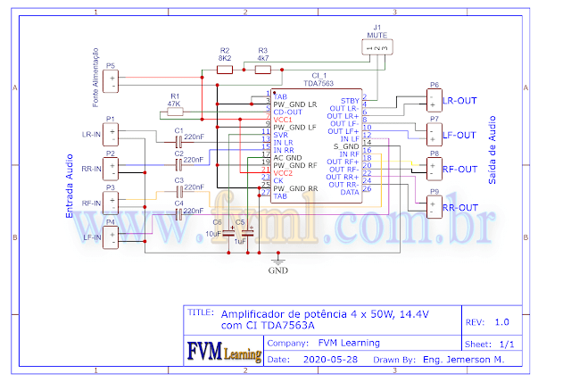
The schematic diagram of the complete circuit, shown in Figure 2 below, is a very robust amplifier, with great sound quality, and very stable, responding very well at all audible frequencies, with little attenuation in the auditory frequency range 20Hz to 20Khz.

Fig. 2 - Schematic 400W Class AB Amplifier using MJL4281A and MJL4302A transistors

Power supply

The power supply is symmetrical, with a voltage of +65V | 0V | -65V, and direct current, with at least 6 Amps of current. For continuous use, we recommend 8A, especially if used in a subwoofer.

In Figure 3 below, we have a suggestion for a power supply that we use in our projects. In this article, besides having the schematic diagram with the Printed Circuit Board, you will understand how to easily calculate your own Power Supply, with the desired voltage.

You can in the link below:

Fig. 3 - Symmetrical Power Supply for Power Amplifiers

Components List

  • Q1, Q2 ............ 2N5401 PNP Transistor
  • Q3, Q4, Q5 ..... 2N5551 NPN Transistor
  • Q6, Q7 ............ MJE340 NPN Transistor
  • Q8 ................... TIP41 NPN Transistor
  • Q9 ................... TIP42 PNP Transistor
  • Q10, Q11 ......... MJL4281 NPN Transistor
  • Q12, Q13 ......... MJL4302 NPN Transistor

  • D1, D2 ............. 1N4007 Diode

  • R1 .................... 56KΩ resistor (green, blue, orange, gold)
  • R2, R3, R14 ..... 100Ω resistor (brown, black, brown, gold)
  • R4 .................... 47KΩ resistor (yellow, purple, orange, gold)
  • R5 .................... 120Ω resistor (brown, red, brown, gold)
  • R6 .................... 1K2Ω resistor (brown, red, red, gold)
  • R7, R12 ............ 680Ω resistor (blue, gray, brown, gold)
  • R8 ..................... 68KΩ resistor (blue, gray, orange, gold)
  • R9, R11 ............ 4K7Ω resistor (yellow, red, purple, gold)
  • R10 .................. 3K9Ω resistor (orange, white, red, gold)
  • R13 .................. 10Ω resistor (brown, black, black, gold)
  • R15 .................. 180Ω / 1W resistor (brown, gray, brown, gold)
  • R16 to R23 ....... 0.22Ω /5W resistor (red, red, gold, silver)
  • R24, R25 .......... 10Ω / 1W resistor (brown, black, black, gold
  • RP1 .................. 1K Potentiometer
  • C1 ........................ 4.7uF / 25V electrolytic capacitor 
  • C2, C7 ................. 100pF ceramic, polyester capacitor
  • C3, C4, C5, C6 .... 47uF / 50V electrolytic capacitor 
  • C8 ........................ 100nF ceramic, polyester capacitor

  • L1 ................ 5uH - Air Core Coil 10 Turns 18AWG, 3/8" Core

  • P1, P2 ........... Screw Terminal Type 5mm 2-Pin Connector
  • P3 ................. Screw Terminal Type 5mm 3-Pin Connector
    • Others ............ PCB, tin, wires, heat sink, soldering Iron, etc.

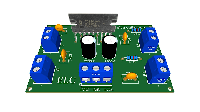
    We are offering the PCB - Printed Circuit Board, in GERBER, PDF and PNG files, for you who want to do the most optimized assembly, either at home. 

    If you prefer in a company that develops the board, you can is downloading and make the files in the Download option below.

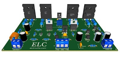
    Fig. 4 - PCB - 400W Class AB Amplifier using MJL4281A and MJL4302A transistors

    Files to download, Direct Link:

    Click on the link beside: GERBER, PDF and PNG files

    If you have any questions, suggestions or corrections, please leave them in the comments and we will answer them soon.

    Subscribe to our blog!!! Click Here - elcircuits.com!!!

    My Best Regards!!!


    Wednesday, December 8, 2021

    24W Stereo Hi-Fi Audio Amplifier using TDA2616 + PCB

    Fig.- 24W Stereo Hi-Fi Audio Amplifier using TDA2616 + PCB

    In this article, we show you how to build a simple and portable 12W + 12W audio amplifier using the TDA2616 Integrated Circuit.

    The TDA2616 IC is a stereo power audio amplifier, it comes with plastic package (SOT131) single-in-line 9-lead (SIL9).

    This IC is explicitly designed for mains powered amplifier circuits, such as stereo radio, instrument return box, TV sets and so on.

    The TDA2616 IC has a good input gain balance on both channels in accordance with IEC 268 and DIN 45500 standards.

    In addition, the TDA2616 has a special integrated circuit for the suppression of noise signals at the inputs during activation and deactivation, which avoids clicking sounds or the famous popping during circuit operation.

    You might also be interested in:

    Features

    • Requires very few external components
    • No switch-on/switch-off clicks
    • Input mute during switch-on and switch-off
    • Low offset voltage between output and ground
    • Excellent gain balance of both amplifiers
    • Hi-fi in accordance with IEC 268 and DIN 45500
    • Short-circuit proof and thermal protected
    • Mute possibility.

    In Figure 2 below, we show the complete 24W Stereo Audio Amplifier Circuit using TDA2616 IC, as we can see, there are few external components, which makes it easier for those who do not have much experience with assembling electronic circuits.

    Fig. 2 - Schematic 24W Stereo Hi-Fi Audio Amplifier with Mute using TDA2616

    Amplifier Operation 

    This amplifier circuit was designed to work with a symmetrical power supply, the maximum power supply voltage is 21V, however the recommended is 16V, with this voltage, an output power of 2 × 12 W is obtained (with THD = 0 .5%) with a load of .

    The mute circuit can also be activated via pin 2. When a current of 300µA is present at pin 2, the circuit is in the mute condition.

    The internal gain voltage is fixed at 30dB, which allows us a stable balance between the two amplifier channels (0.2dB).

    Components List

    • U1 ....................... TDA2616 Integrated circuit

    • R1, R2 ................ 8.2Ω resistor (brown, black, orange, gold)

    • C1, C2 ................ 470nF ceramic, polyester capacitor 
    • C3, C4 ................ 22nF ceramic, polyester capacitor 
    • C5, C6 ................ 2200uF / 25V electrolytic capacitor

    • P1, P2, P3, P4 .... Screw Terminal Type 5mm 2-Pin Connector
    • P5 ....................... Screw Terminal Type 5mm 3-Pin Connector
      • Others ................ PCB, tin, wires, soldering Iron, etc.

      Download

      We provide the files with the PCB, the schematic, the PDF, GERBER and JPG, PNG and provide a direct link for free download and a direct link, "MEGA".

      Fig. 3 - PCB - 3D - 24W Stereo Hi-Fi Audio Amplifier with Mute using TDA2616

      Click on the direct link to download the files: Layout PCB, PDF, GERBER, JPG

      If you have any questions, suggestions or corrections, please leave them in the comments and we will answer them soon.

      Subscribe to our blog!!! Click here - elcircuits.com!!!

      My Best Regards!!!


      Friday, December 3, 2021

      5W Stereo Audio Amplifier Circuit using TEA2025 IC + PCB

      In this article, we show you how to build a simple and portable 5W stereo audio amplifier using the TEA 2025 Integrated Circuit.

      This circuit built based on TEA2025 IC which is a monolithic integrated audio amplifier in a 16-pin plastic dual in line package manufactured by UTC

      The circuit has Internal Thermal Protector. It is designed for portable cassette players, mp3 players and radios. 

      You can also use it as your smartphone or PC audio amplifier. This circuit requires 9V power supply to work, you may use a power supply circuit with output 9V 500mA DC current or a 9V lead acid battery.

      Features

      • The power supply voltage range is from 3V to 15V.
      • Working Voltage down to 3V
      • Few External components
      • Dual or Bridge Connection Modes
      • High Channel isolation
      • Very low switch On/Off Noise
      • Voltage gain up to 45dB(Adjustable with external resistor)
      • Soft clipping
      • Internal Thermal protection

      Working Explanation

      This amplifier, in the configuration presented in this article, is 2 channels, has an output power of 2.5 watts per channel.

      For those who want to use a single channel, you can be using it in bridge mode, and you will have an output power of 5W.

      Input Capacitor

      The input capacitor is PNP type, allowing the source to be referenced to ground. In this way, no input coupling capacitor is required. 

      However, a series capacitor (0.22 uF)to the input side can be useful in case of noise due to variable resistor contact.

      Bootstrap

      The bootstrap connection allows increasing the output swing. The suggested value for the bootstrap capacitors (100uF) avoids a reduction of the output signal also at low frequencies and low supply voltages.

      This amplifier in this 2-channel configuration, has an output power of 2.5 watts per channel, and you may be using it in bridge mode, and you will have an output of 5W.

      Power supply

      The power supply is direct current, "Vdc", the voltage supported by this amplifier is up to 15V, with a peak current of 1.5 amps.

      The voltage input pin is located on pin 16 of  TEA2025 IC, while pins 4, 5, 9, 13, 12 are grounded to GND.

      Applications

      • Electronic Instruments
      • PC sound speaker
      • Home theater systems
      • Hi-fi electronic gadgets and devices
      • Robotics applications 
      • Children’s gadgets and toys, etc.

      In Figure 1 below, we show the complete 5W Stereo Audio Amplifier Circuit using TEA2025 IC, and that you can download the files in option; Download files below at the bottom of the page.

      Fig. 1 - Schematic 5W Stereo Audio Amplifier Circuit using TEA2025 IC

      Components List

      • U1 ................................ TEA2025 Integrated circuit

      • R1, R2 ......................... 10K resistor (brown, black, orange, gold)

      • C1, C2 ......................... 0.47uF ceramic, polyester capacitor 
      • C3, C4, C5, C6, C9 ..... 100uF electrolytic capacitor
      • C7, C11 ....................... 470uF electrolytic capacitor
      • C8, C10 ....................... 0.15uF ceramic, polyester capacitor 

      • P1, P2, P3, P4, P5 ....... Screw Terminal Type 5mm 2-Pin Connector
      • Others ......................... PCB, tin, wires, etc.

      PCB - Download

      We provide the files with the PCB, the schematic, the PDF, GERBER and JPG, PNG and provide a direct link for free download and a direct link, "MEGA".

      Fig. 2 - 5W Stereo Audio Amplifier Circuit using TEA2025

      Click on the direct link to download the files: Layout PCB, PDF, GERBER, JPG

      If you have any questions, suggestions or corrections, please leave them in the comments, and we will answer them soon.

      Subscribe to our blog!!! Click here - elcircuits.com!!!

      My Best Regards!!!

      Tuesday, October 12, 2021

      180W RMS 4-Channel Amplifier using TDA7386 + PCB

      Fig 1 - 180W RMS 4-Channel Amplifier with TDA7386 PCB

      Para versão em Português, Clique Aqui!!!

      The TDA7386 four-output integrated circuit is a class AB amplifier rated at 180W RMS "unbalanced power supply" in a single package with few external components.

      This audio amplifier is designed for Sony®, Kenwood®, Pioneer® and other high performance car radios.

      Features

      • High output power capacity:
      • 4 x 45W / 4Ω max.
      • 4 x 28W / 4Ω @ 14.4V, 1KHz, 10%.
      • 4 x 24W / 4Ω @ 13.2V, 1KHz, 10%
      • Low distortion
      • Low output noise
      • Stand-by function
      • Mute function
      • Auto- mute function when minimum supply voltage is detected
      • Low number of external components:
      • Internal fixed gain (26dB)
      • No external compensation
      • No bootstrap capacitors

      You might also be interested in:


      Based on the TDA7386 IC, it is also ideal for use in home studio amplifiers, computers with quadraphonic sound cards such as SoundBlaster Live! Creative Labs Inc. or MosterSound Diamond Multimedia / S3, Active Box, home theater, etc...

      Each channel of the TDA7386 provides 45W RMS with a sufficient power of 14.4 volts, at a load of 4 ohms and a distortion factor of about 10%.

      The amplifier schematic shown in Figure 2 is a simple design with few external components, making it an easy amplifier to build.
      Fig. 2 - 180W RMS 4-Channel Amplifier with TDA7386 Schematic

      Components List

      • IC 1 ..................... Integrated circuit TDA7386
      • R1  ...................... 47K resistor (yellow, purple, orange)
      • R2  ...................... 10K resistor (brown, black, orange)
      • C1, C2  ............... 1μF electrolytic capacitor
      • C3 ....................... 100nF electrolytic capacitor
      • C4  ....................... 220μF electrolytic capacitor
      • C5, C6, C7, C8  ....100nF electrolytic capacitor
      • C9  ....................... Electrolytic capacitor 470nF
      • C10  ..................... Electrolytic capacitor 47μF
      • B1  ....................... 2-Pin Board-Cable Connector
      • B2 ........................ 5-Pin Board-Cable Connector
      • B3, B4, B5, B6  ... 2-pin board cable connector
      • Others .................. PCB, tin, wires, etc.

      Power supplies

      For lovers of amplifiers with IC, it is best to have a simple power supply, because many have simple variable test bench sources that make testing much easier, in addition to an audio amplifier power for the car, we will necessarily have the simple power supply.

      Since this amplifier operates at low voltage, the consumption is quite high. According to Ohm's law, we can calculate this current as follows, using the formula.
      P = V * I

      Where;
      • P = power, V = voltage, I = current.
      Soon;
      • I = P / V
      • I = 180/14.4
      • I = 12.5 A
      Due to the high current consumption indicated in the above formula, the connections to ground and to the power supply must be made with extreme care.

      In car radios, the heat sink is small, but it is in contact with the radio housing, which is made of metal, which greatly facilitates heat dissipation.

      For home amplifiers, which are usually in constant use, a good heat sink should be used. "It depends on how you are going to use it," you say, putting a cooler on the heatsink like the ones used in ATX computers.

      Download

      We provide the files with the PCB, the schematic, the PDF, GERBER and JPG, PNG and provide a direct link for free download and a direct link, "MEGA".

      Click on the direct link to download the files: Layout PCB, PDF, GERBER, JPG


      If you have any questions, suggestions or corrections, please leave them in the comments and we will answer them soon.

      Subscribe to our blog!!! Click here - elcircuits.com!!!

      My Best Regards!!!

      Friday, October 8, 2021

      4 x 50W High Power Amplifier, 14.4V - IC TDA7563A + PCB

      Fig 1. - PCB 4 x 50W High Power Amplifier, 14.4V - IC TDA7563A

      Para versão em Português, Clique Aqui!!!

      This is a 200W High Power Amplifier Circuit, and its great trump card is that it works with a simple power source and still at 14.4V, which means we can plug in a 12V car battery, or motorbike battery, or UPS battery, etc.

      Also, the circuit is very easy to build as it requires very few external components.

      The TDA7563A is a quad-bridge type amplifier of BCD technology in Flexiwatt27 and Power SO36 packages designed specifically for car radio applications.

      Thanks to the DMOS output stage, the TDA7563A has very low distortion, which allows for clear and powerful sound. 

      Features include its superior efficiency performance resulting from the unique internal system structure, making it the device best suited to simplify thermal management in high power packages.

      This device is equipped with a complete diagnostic matrix that communicates the status of each speaker via the I2C bus.

      You might also be interested in:

      Features

      • Multiple Power BCD Technology
      • MOSFET output power stage
      • DMOS power output
      • New high efficiency technology (SB class)
      • High output power capacity 4x28W / 4Ω @ 14.4V, 1kHz, 10% THD, maximum power 4x50W
      • Maximum output power 4x72W / 2Ω
      • Complete conduction of I2C bus:
      • Standby
      • Front/rear independent, smoothed play/mute
      • Selectable 26dB / 12dB gain (for low noise line output function)
      • Enable / disable high efficiency
      • I2C bus digital diagnostics (including DC AC load detection)
      • Total failure protection
      • DC offset detection
      • Four independent short circuit protection
      • Cutting Detector Pin with Selectable Threshold (2% / 10%)
      • Standby/mute pin
      • Linear thermal shutdown with multiple thermal warnings
      • ESD protection

      In Figure 2 below, you can see the schematic of the High Efficiency Power Amplifier. We can understand and analyze the simplicity of the circuit and see that it is an easy to assemble circuit with few external components.

      Fig 2 - Schematic Diagram 4 x 50W High Power Amplifier, 14.4V - IC TDA7563A

      Power Supply

      This amplifier is powered by a single positive and negative voltage power supply and has a supply voltage range that varies with a minimum voltage of 8V and a maximum voltage of 18V

      The typical working voltage with no load on the integrated circuit is 14.4V.

      The power supply must have a current of at least 5 amps to be used in mono mode, when mounted in stereo version, "two channels", the current must be doubled, and it must also be provided with a good filtering to avoid a ripples system that can cause noise in the amplifier.

      The working impedance value of this amplifier to reach its total power is 4 ohms, but we can also set it to 8 ohms, but then we will not get the maximum power from the amplifier.

      Components List

      • CI1 ......................... Integrated Circuit TDA7563A
      • C1, C2, C3, C4 ...... 220nF Ceramic / Polyester Capacitors
      • C5 ........................... Capacitors 1uF / 63v
      • C6 ........................... Electrolytic Capacitor 10uF / 63v
      • R1 ........................... 47K Ohm resistors
      • R2 ........................... 8K2 ohm resistor
      • R3 ........................... Resistor 4K7 ohms
      • P1 to P9 .................. KF301 solderable 2-Pin Bolt-On Connector (Optional)
      • J1............................. 3 Ways 1x3 Weldable Male Pin Bar
      • Others ..................... Heatsink for IC, wires, connectors, PCI, tin etc.

      We provide the files with the PCB, the schematic, the PDF, GERBER and JPG, PNG and provide a direct link for free download and a direct link, "MEGA".

      Direct Download Link

      Click on the link to download the files: Layout PCB, PDF, GERBER, JPG

      If you have any questions, suggestions or corrections, please leave them in the comments and we will answer them soon.

      Subscribe to our blog!!! Click here - Elcircuits.com!!!

      My Best Regards!!!