|
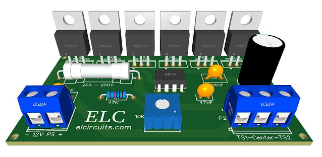
| Fig.1 - 12-36V 60A PWM DC Motor Speed Controller Using LM555 With PCB |
The main reason for using pulse width modulation in DC motor control is to avoid excessive heat dissipation, as in linear power control circuits.
Since in linear circuits there is a huge problem with heat dissipation. PWM control circuits greatly reduce this issue because of their much higher power conversion efficiency.
The circuit that we are going to build is a simple circuit, with the principle of operation by PWM control, based on the LM555 generator, already well known and with a super affordable price in the market.
It is a width modulation control, which can be controlled through a potentiometer, or trimpot, or even with fixed resistors, this will depend on your project.
Speed Control
There are several techniques used to control the speed of a motor, due to the demand of thousands of applications in industry, there has been a great need to control these speeds.
Long ago, when the technology of speed control did not exist electrically, industrial equipment had its speeds altered or adjusted mechanically, by means of stepping pulleys, change gear sets, variable speed friction clutch mechanism and other mechanical devices.
Electric speed control has many advantages both economically and engineering over mechanical speed control.
The speed control for motor drives, depend on their type. Some drives require continuous speed variation for the entire range from zero to maximum speed, others demand a portion of this range, while others may require two or more fixed speeds.
How PWM Works
Pulse Width Modulation control works by very quickly turning on and off the power supplied to the motor.
The DC voltage is converted into a square wave signal, alternating between fully on (Vdc Max) and zero, giving the motor a series of "kicks" of power.
Pulse width modulation (PWM) is a speed control technique that can overcome the problem of poor starting performance of a motor.
PWM for motor speed control works in much the same way. Instead of supplying a variable voltage to a motor, it is supplied with a fixed voltage value (Vdc Max) that causes it to spin immediately.
The voltage is then removed and the motor "coasts". By continuing this on/off voltage cycle with a variable duty cycle, the speed of the motor can be controlled.
How the Circuit Works?
The U1 is wired as a low-frequency, free-running Astable Multivibrator with Pulse Width Modulation (PWM). The R-C components like R1, VR1 and C1 determine the frequency oscillations.
When the wiper arm of potentiometer VR1 is in top position, capacitor C1 charges through R1 and D1/D2 and produces a pulse train at the IC's output with long negative and short positive pulse widths.
Therefore, the motor speed is slow. On the other hand, when the wiper arm of VR1 is at the bottom position, C1 charges through R1 and discharges via VR1 The resulting pulse train has long positive and short negative pulse widths.
Now the motor rotates at a high speed. The IC's output at pin 3, is fed to transistors pair, Q1 and Q2, which, in turn, drives the DC motor through high power switching MOSFETs Transistor Q3-Q6 at the selected speed. Resistor R4-R7 limits the base current of power transistors.
The Zener diodes D4 to D7 are 15V diodes, they serve to stabilize the base voltage of the Mosfet transistors, since they are very sensitive to gate voltages.
Diode D8, connected in antiparallel with the DC motor, limits the back E.M.F. generated by the rotation of the motor.
The Power Supply
The control circuit is powered from a power supply formed by the LM317HV IC, this IC is a high voltage regulator, which receives voltages up to 60V and is set to a stabilized 9V output voltage to power the control circuit.
This is important since the LM555 IC supports voltages up to 16V, and our circuit operates with voltages ranging from 12V to 36V.
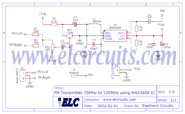
The Schematic Circuit
The circuit diagram of the power amplifier is shown in Figure 2 below. It uses 8 output Mosfet power transistors, 4 transistors for the positive cycle and 4 transistors for the negative cycle.
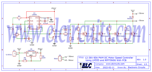 |
| Fig. 2 - Schematic Circuit 12-36V 60A PWM DC Motor Speed Controller Using LM555 |
Components List
- Semiconductors
- U1 .......................... LM555 Integrated Circuit
- U2 .......................... LM317HV High Voltage Regulator
- Q1 .......................... BD140 PNP Transistor
- Q2 .......................... BD139 NPN Transistor
- Q3, Q4, Q5, Q6 ..... RFP70N06 Mosfet Power Transistor
- D1, D2, D3 ............ 1N4007 Silicon Diode
- D4, D5, D6, D7 ..... 1N4744 15V Zener diode
- D8 .......................... 1N5408 3A Silicon Diode
- Resistor
- R1 ......................... 1KΩ (brown, black, red, gold)
- R2 ......................... 33Ω (orange, orange, black, gold)
- R3 ......................... 10KΩ (brown, black, orange, gold)
- R4, R5, R6, R7 ..... 10Ω (brown, black, black, gold)
- R8 ......................... 240Ω (red, yellow, brown, gold)
- R9 ......................... 1K5Ω (brown, green, red, gold)
- VR1 ...................... 250KΩ Variable resistor
- Capacitor
- C1 ......................... 100nF Ceramic Capacitor
- C2 ......................... 10nF Ceramic Capacitor
- Miscellaneous
- P1, P2 ................... 2-pin PCB soldering terminal blocks
- Others ................... Printed Circuit Board, heat sink, wires, etc.
We are offering the PCB - Printed Circuit Board, in GERBER, PDF and PNG files, for you who want to do the most optimized assembly, either at home.
If you prefer in a company that develops the board, you can is downloading and make the files in the Download option below.
 |
| Fig. 3 - PCB - 12-36V 60A PWM DC Motor Speed Controller Using LM555 |
Files to download, Direct Link:
Click on the link beside: GERBER, PDF and PNG files
If you have any questions, suggestions or corrections, please leave them in the comments and we will answer them soon.
Subscribe to our blog!!! Click Here - elcircuits.com!!!
My Best Regards!!!